Electromagnetic Levitation
Understanding how electromagnetic levitation works and how to control stability
1. Levitation using electromagnets
Can a magnet levitate or float above another magnet? Why not - it seems like it should work!
Sadly, you can't make a magnet magically float in the air above another magnet. At least, that's true if you're using just a pair of strong magnets. In our Magnet Basics article, we mentioned Earnshaw's Theorem, which is proof dating back to the 1800s which states it won't work no matter how many magnets you add to the system.
But what if the magnets are shaped like a bowl? Or another magnet is added on the side? Nope. Earnshaw.
Let's examine a system that somehow sidesteps around old Earnshaw, and manages to keep a magnet floating steadily in the air. It can even hold a small amount of weight!
Hang on – things get more complicated from here.
First, let's see electromagnetic levitation in action
2. Products that utilize magnets for levitation
We've seen a number of products that use this system. These things seem to catch the eye of social media. We've seen levitating globes, where the earth levitates in the air somehow.
We've even seen the same technique used to levitate a small bonsai tree! So cool.


Shop Neodymium Magnets
Pyrolytic graphite and other magnets perfect for basic levitation experiments.
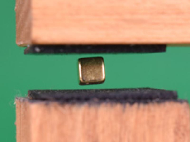


3. Simple levitation using a tube
The basic idea is to make a magnet float by holding it up with the repelling force from another magnet. Magnets can repel each other with enough force. Having enough force to levitate it isn't the problem.
The problem is that this setup isn't stable. The floating magnet tends to rotate around, flipping itself to attract to the other magnet.
This is true even if you line a bowl with a bunch of magnets, because of the Earnshaw theorem.

Two D84 disc magnets repel one another, but must be constrained in the tube for stability.
4. How to stabilize magnets when levitating
Let's take a moment to define what we mean by stability. A stable system is something that is balanced, but also tends to go back to the centered, balanced position if you bump it a bit.
As an example, consider a long stick or pole, held from the top. It's stable hanging straight down. If we push the bottom away from a straight down position, gravity will tend to pull it back to the stable position.
A stick held from the top is naturally stable. Push the bottom off-center and gravity pulls it back to the stable position.
Sure, it might not snap in place on the first swing. It will swing back and forth for a bit, with successively shorter swings as it settles down. It will return eventually after momentum has ceased.
An unstable system is something that can be balanced, but if it gets off-balance, it tends to get more unbalanced. Consider holding the same stick with your hand held flat at the bottom. It's possible to balance it, but when the stick leans off balance, it tends to fall more off balance.
You can hold a stick like this, but only by constantly adjusting your hand position to keep it balanced. You watch and feel which way it's falling and react by moving your hand to counter it. You watch and react, repeating continuously. Interestingly enough, the levitating magnet setup works in much the same way.
A stick held from the bottom is unstable. Once it starts to tip, gravity will make it tip more. Only by reacting and moving your hand can you hold it upright.
5. Electromagnets, Sensors, Feedback and Control
Let's get back to levitating a magnet. How does this device hold it steady?
In addition to repelling magnets, this levitator has four electromagnets. If the floating magnet tips one way, it can quickly turn on an electromagnet to repel it back into the centered position. If the system can react quickly enough, the electromagnets can be switched on and off as necessary to hold the magnet steady. The nice thing about electromagnets is that they're run with a current through the wire. If you know how to switch things on and off with electronics, you have a means of controlling the electromagnet quickly and accurately.
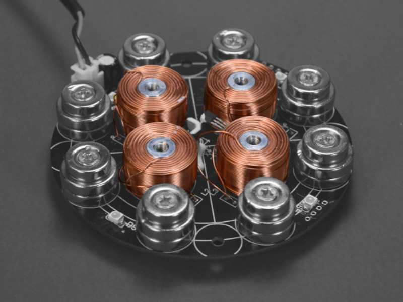
The four copper windings around steel shafts are electromagnets.
This system does not violate Earnshaw's theorem because it's not using some number of permanent (always on) magnets to hold up the floating magnet. It has actively controlled magnets that are switched on and off, responding to mis-alignment and correcting the instability.
6. Temporary magnets
First, let's take a closer look at the odd setup used in the base of this thing. With the power turned off, where are the magnets and which way are they facing? There are three different places where we should look at the magnetization direction:
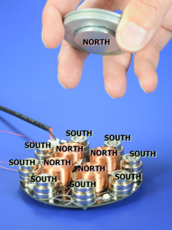
- We see a series of magnets arranged in a ring around the outside. They are all oriented with their south poles facing up.
- There's a single disc magnet on the bottom of the floating magnet, oriented with its north pole facing down.
- There are four electromagnets which are coils of insulated wire wrapped around steel shafts. Due to the field of the nearby ring of magnets, these steel cores are temporarily magnetized, acting like magnets with their north poles facing up.
Wait, what's going on in that last part? They're not magnets but they are?
Steel or iron can act as a temporary magnet. When a magnetic field is applied to it (stick a magnet to it or near it), the field channels through the steel, making the steel act like a magnet (as long as that magnet is there). This is like the string-of-paperclips trick, where a paperclip with a magnet stuck to it can pick up another paperclip because it's acting like a magnet. We can look at the steel paperclip and say it has a north and a south pole.
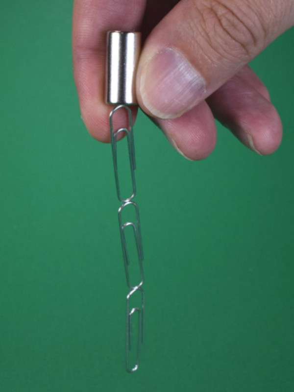
In the above classic example, steel paperclips act like temporary magnets themselves, as long as one is touching the powerful neo magnet.
A steel bolt acts like a magnet when a neodymium magnet is touching it. A steel bolt can also act like a magnet just by having a neodymium magnet near it. That's what's going on here in this device. Those steel cores act like magnets with their north poles facing up, repelling the floating magnet's north pole.
When powered on, the electromagnets can add to the strength of those magnets as necessary.
The system is not stable by itself. If you try to balance the floating magnet without powering the device on, it quickly snaps off to the side.
Why was such a seemingly complex setup chosen for this design? Good question. We think it might have something to do with making a wider area where the floating magnet can be almost stable, set in the "bowl" of the magnetic field going from the north poles in the middle, up over and down into the south poles at the outside.
With a strong magnet stuck to it, the steel bolt acts like a magnet, able to pick up a steel nut in the below video.
In a setup much like this device, a steel bolt with a magnet nearby (separated by a thin stack of PostIt notes) can act like a magnet too in the above video.
7. Using sensors to control levitation
In order to control the electromagnets properly, the device needs a way of accurately sensing the position of the floating magnet. It needs to notice the tiniest change in position so that it can react quickly.
In this device, three ratio metric hall effect sensors are used. In a previous article about Hall effect sensors, we looked at simple devices that are essentially on/off switches. If they “see” a magnetic field that's above a certain strength, they switch on.
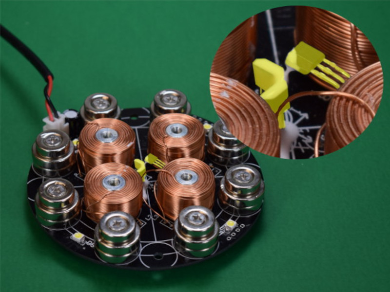
Three Hall effect sensors, highlighted in yellow, provide magnetic field measurements in each primary axis in the above picture.
The ratio metric sensors used here are different. Instead of a sensor that flips on or off at a certain field strength, the tiny chips supply a voltage that varies with the strength of the magnetic field it sees. If the magnetic field gets stronger, the voltage goes up. They're great for sensing tiny changes in magnetic field strength.
Magnets with a bigger Maximum Energy Product will have greater strength. Specifically, the shape of the BH Curve indicates both how strong a magnet is and how strong of a magnetic field you would need to demagnetize the magnet.
There are three of these sensors located at the center of the device. They are oriented to sense the magnetic field in each direction: up and down, left and right, fore and aft. Armed with a bit of magnetic knowledge, the readings from these three sensors provide enough information about the height and position of the floating magnet.
When the floating magnet tips off to the side, the system can sense it from these inputs and turn on the right electromagnet to give it a correcting push.
8. Stabilization control for electromagnetic levitation
This device has three sensors and four separately controlled electromagnets. Let's take a peek at just a small part of the system to get an idea of what's going on. We hooked up an oscilloscope to two interesting points:
- The voltage out from one of the sensors pointing laterally (not the up-down sensor).
- The voltage on one of the coils (in that same direction).

An oscilloscope reveals one sensor's signal in yellow, and the voltage applied to one electromagnet in blue in the above picture.
The sensor signal, shown in yellow, is very noisy. Ignore the noise, though, and just look at the overall voltage level. We saw that it gets higher or lower depending on the position of the magnet. It sits around 1.75 volts, but changes a tiny amount as we pressed on the magnet. The changes are just a few millivolts, even when we're drastically pushing the magnet around.
The blue signal shows the voltage to one of the electromagnet coils. It goes up to about 2.5 V and back to zero. It's either on or off. It switches on every 1/100,000th of a second.
Rather than adjusting the strength, the control circuitry varies how long it leaves that coil on during that 1/100,000th of a second. If it doesn't need much push, it's on maybe 5% of the time. When we touch the floating magnet, it goes on longer. You can see this in the width of the up-time signal.
This control of the electromagnet flips on and off at 100 kHz. That's 100 kiloHertz, or 100,000 times per second. That's really fast!
We had hoped to hook this signal into a speaker to allow us to hear it as sound. It would be neat to hear that interactive audio feedback. Sadly, 100 kHz is far above the highest frequency humans can hear. It's even above a dog's ability to hear it! We would have to either downsample the signal, or ask some dolphins what they think about it.
That's a look at just one sensor and one of the four electromagnets. The other three are working in similar ways to counteract tilts in the other directions.
In addition to using the four electromagnets individually to prevent the floating magnet from tipping away in any direction, the whole system must also control the overall signal level to all four electromagnets. That's going to influence the height of the floating magnet above the base.
Conclusions
We've had a lot of fun trying to figure out how this device works. The more we figured out, the more we found whole topics we hadn't even considered. For example:
- The system is sensitive to the weight of the floating magnet. If it's too light, it won't work well. It needs some minimum weight for the way it's setup.
- There's a steel washer above the thin floating magnet. This obviously provides ballast, but it also has a real effect on the shape of the magnetic field. In some testing, we found we couldn't get a magnet to float without this steel disc on top, flattening the field. Why does this arrangement work so well? Why not just a magnet with non-ferrous ballast?
We've often tried to explain how complicated magnetic levitation can be, we had no idea how much more it involved!
9. Simpler ways to achieve electromagnetic levitation
Addendum: A much simpler system
We have a levitation kit we acquired years ago that has a much simpler setup. Check out the ART TEC Magnetic Levitation Kit by Guy Marsden.
This setup flips the system upside down, making things a lot easier. It has a single electromagnet positioned above the floating magnet. The electromagnet flips on and off to control the vertical position of the magnet.
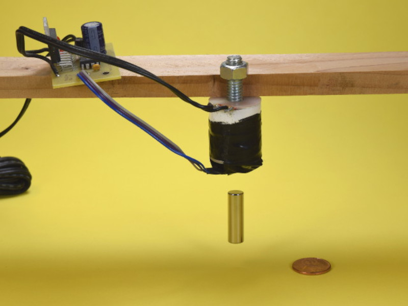
A D5X0 cylinder magnet hanging beneath the electromagnet in the above picture.
Since the magnet is “hanging” below, it tends to be naturally stable side-to-side. Like a long pole hanging down, you get natural stability in this configuration. The system doesn't have to do anything fancy to control lateral movement.
We hooked this one up to the oscilloscope as well and found a different control scheme. Rather than switching the electromagnet on and off at fixed intervals, it turns on and off as necessary, reacting to the sensor's measurement. When the magnet starts getting too low, it turns on to pull it up. When the magnet starts getting too high, it turns off.
The frequency of this on and off switching varies depending on what the sensor says. We found that the frequency changed as we tried hanging different magnets and/or different weights from it.
When you see electronic products that levitate something using one of these two basic setups, you can usually figure out which one it is. If there's something above the floating object, it's this second, simpler system. If there's nothing above the floater, it's the first.


