Homopolar Motors


Neodymium magnets are used in electric motors all around us. From the motor that spins a DVD disc to the wheels of a hybrid car, permanent magnets are used in motors everywhere.
While there are many types of electric motors, K&J Magnetics takes a look at one of the simplest types: the Homopolar Motor.
What force makes a motor turn?
Many articles and books on this subject often begin with a historical perspective, recounting how some of the science behind electric motors was discovered. We'll skip that here to keep things brief, but read more about Michael Faraday, Faraday's Law, the Lorentz force and even Fleming's left hand rule for motors for more interesting information about the history of electric motors and how they were discovered.
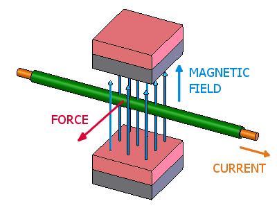
The science behind electric motors boils down to this: If you have an electric current flowing through a wire that happens to be in a magnetic field, it feels a force push on it.
Specifically, if you have a straight piece of wire sitting in a magnetic field as shown at right, the wire will feel a force pushing on it as shown, at right angles to both the wire and the magnetic field.
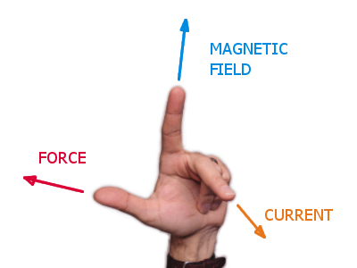
If you use the left-hand rule to help figure out the direction of the force, follow these conventions:
- The direction of the magnetic field is from a north to south
- The direction of the electric current is that of conventional current, from positive to negative
Homopolar Motors
Homopolar motors were first invented by Faraday, and is perhaps the most simple type of electric motor. It isn't very useful because it uses very high electrical currents, has poor efficiency and a few other factors. You just can't get much useful power out of it. One thing it is good for is a great demonstration or subject of a science report.
Demonstration A
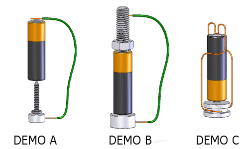
To demonstrate the homopolar motor in action, we will show motors in 3 different configurations. The first is very simple to make, using only an AA battery, a steel screw with a pointed end, a short, 9" long piece of solid wire and a neodymium magnet. We used two D82 magnets stuck together in the video below. A single D84 magnet would be the same, though we found it would work even with a single D82 magnet.
In this configuration, we hold the current-carrying wire still, along with the battery, and the magnet and screw spin. This is fairly easy to reproduce, though we had some problems with the screw slowly migrating off to the side. We solved this by adding a piece of tape with a hole in it. We have seen other videos where the battery was hit with a chisel or other sharp object to make a small indentation for the screw-point to sit in.
Demonstration B

In this second setup, we hang the battery and magnet beneath a stationary steel bolt. The magnet-battery combination sticks to the bolt because a bit of the magnetic field goes up through the battery. We used the same AA battery, the same piece of wire, and a single DC6 magnet.
This produced some obvious results, with the battery spinning out of control. This is a good way to demonstrate the motor in front of a large group, where you need motion that's more obvious from a distance.
Demonstration C
This is the most common setup we've seen, but we chose to present it last. It can be challenging to come up with a stable configuration of the wire that allows it to spin well without falling off. Be prepared to fiddle with the wire a bit to get it right.
Use a piece of solid (not stranded) wire. We used 18 gauge wire, though other sizes would work as well. We removed all the insulation from the wire before experimenting with it. Technically, you only have to remove the insulation where it contacts the battery and the magnet, but removing it all seemed easier.
You don't have to use a magnet with a stepped groove in it, but we found it helpful to get the wire to stay in contact with the magnet this way. We used our SDC6-IN magnet, though you could use a plain disc like the DC4 or DC6 just as well. You can even use smaller discs like the DA2 for this demonstration.
When describing how a homopolar motor works, most explanations describe it in terms of a force acting on the wire. This demonstration clearly shows the wire moving, so it makes matters more obvious and jives well with the technical explanation.
Limitations, Conclusions and Further Thoughts
Homopolar motors are useful for demonstrating electromagnetic forces and explaining the concepts behind how motors work. As an actual useful motor, don't expect much from it. You won't find a homopolar motor providing much useful work in common applications around you.
Why not? Because it only has one winding - one loop of wire. To get the motion, there are really high currents flowing through the wire. It's practically just shorting the battery out. It's so much current, the battery gets used up within a minute or two. It's a hugely inefficient use of the battery, demanding much more current than these batteries are really designed for.
Caution: With this much current flowing, things get hot quickly. The wire and the battery can become dangerously hot, so handle with care.
Motors vs. Generators
We receive a lot of questions about motors and generators, but keep in mind that their design can be very much the same. In the motor, an electrical current makes something move. Put electricity in and the motor turns that into motion.
A generator is the opposite: Motion from some outside power source gets turned into current through a wire. Turn the crank by hand, and the motor supplies electricity.
Many electric motors can be used to demonstrate this idea. If you take a motor and turn the shaft by hand, you can make electricity. Hopefully we'll demonstrate this in a future motor/generator article!
Unfortunately, homopolar motors made with a piece of wire can't be turned into a good generator. You just don't get enough voltage out of it. In our Shake Flashlight article, we used a big magnet moving through a coil of wire with over a thousand turns of wire in the coil, which produces a higher voltage. A homopolar generator actually uses a disc of conducting material instead of a wire, like Faraday's original generator experiments in 1831.


