Reed Switches and Hall Effect Sensors
Magnetic sensors are used in everything from cars to cellphones. What magnet should I use with my magnetic sensor? Should I use a Hall effect sensor or a reed switch? How should the magnet be oriented to the sensor? What tolerances should I be concerned with? Learn more with a K&J walk-through of specifying a magnet-sensor combination.
What is a Reed Switch?

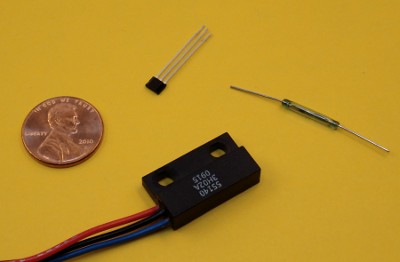
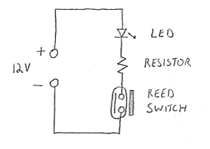
The reed switch is an electrical switch operated by an applied magnetic field. It consists of a pair of contacts on ferrous metal reeds in an airtight glass envelope. The contacts are normally open, making no electrical contact. The switch is actuated (closed) by bringing a magnet near the switch. Once the magnet is pulled away, the reed switch will go back to its original position.
What is a Hall Effect Sensor?
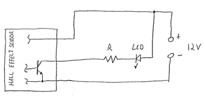
A Hall effect sensor is a transducer that varies its output voltage in response to changes in magnetic field. In some ways, Hall effect sensors can ultimately perform a similar function as a reed switch, but with no moving parts. Think of it as a solid-state component, good for digital applications.
Which of these two sensors is right for your application depends on a number of things. Factors include cost, magnet orientation, frequency range (reed switches typically aren't usable over 10 kHz), signal bounce and the design of the associated logic circuitry.
Magnet - Sensor Orientation
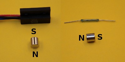
A key difference between reed switches and Hall effect sensors is the proper orientation required for an activating magnet. Hall effect sensors activate when a magnetic field that is perpendicular to the solid-state sensor is applied. Most look for the magnet's south pole to be facing an indicated location on the sensor, but check the specification sheet of your sensor. If you turn the magnet backwards or sideways, the sensor won't activate.
Reed switches are a mechanical device with moving parts. It consists of two ferromagnetic wires separated by a small gap. In the presence of a magnetic field that is parallel to those wires, they will touch each other, making electrical contact. In other words, the magnetic axis of the magnet should be parallel to the long axis of the reed switch. Hamlin, a manufacturer of reed switches, has an excellent application note on the subject. It includes great diagrams showing the areas and orientations in which the sensor will activate.

It should be noted that other configurations are possible and often used. For example, Hall effect sensors can detect steel blades of a spinning "fan." The steel blades of the fan pass between a stationary magnet and stationary sensor. When the steel is between the two, the magnetic field is redirected away from the sensor (blocked) and the switch opens. When the steel moves away, the magnet closes the switch.
What size magnet do I need?
The spec sheet for your sensor should indicate the magnetic field strength required to activate the switch. This number is usually between 10 and 100 gauss, but check your specs. Also note that some sensors are specified in AT, or Ampere Turns. The relationship between gauss and AT is complicated, but can be approximated as 1 gauss = 1 AT. It isn't perfect, but it will get you close. Again, Hamlin has a good application note on this.
For Hall effect sensors, determine the distance from the surface of the magnet where the minimum strength requirement is met. In the video below, we used a Hamlin 55410-3H-02-A Hall effect sensor purchased from DigiKey. The spec sheet indicates a typical activation sensitivity of 59 gauss. For a particular magnet, what distance gives me at least 59 gauss? This question is easily answered using our Magnet Calculator. Input the diameter and thickness of a disc magnet, and try different distances until it matches the spec number.
In our example, a D42 magnet will create a magnetic field with a field strength of 59 gauss at 0.53 inches away from the face of the magnet. In practice, a margin of error is often figured in. A magnet or distance is chosen where the strength is well above the theoretical number, often at 125% or 150% of that value. Since the sensor remains activated if the field is well above the minimum number, this is a safe practice.
For reed switches, the magnet is positioned with the magnetization axis parallel to the sensor. You need to know the strength of the magnetic field at some distance away from the side of a disc/cylinder magnet, not from the face. Since our Magnet Calculator doesn't provide this data, and there isn't an easy formula, approximate by multiplying the Calculator's answer by 0.5.
UPDATE: Since this article was posted, we've added a new calculator that can estimate the field strength around disc/cylinder magnets both on and off the central axis. While the above approximation is still valid, our Magnetic Field Calculator can also be used.
In our example, we're using a Hamlin MDCG-4 reed switch, also available at DigiKey. The spec sheet indicates it will activate in a range between 12 to 38AT. Assuming that's equal to 12 to 38 gauss, I plug some numbers into the Magnet Calculator to find the range of distances I might expect a D42 magnet to activate this sensor from. Since the sensor will be off to the side, I'm looking for the calculator distance for double those numbers, or 24 and 76 gauss. For this magnet and sensor, expect it to activate somewhere between 0.48 and 0.74 inches.
Demonstrations
Enough theory, let's see these sensors and magnets in action. For both sensors, we have calculated the distance for three different magnets: a D42, a D55 and a huge DX0X8. Those calculated values are shown sketched on the paper in the video. These may not be the magnets you want to use, but the wide range makes for a good visual demonstration. Designers often select magnets that are as tall as they are wide, such as D22, D33, and D44.
The Reed Switch:

The Hall Effect Sensor:

Engineering Tolerance Issues
A question we're often asked about: What is the tolerance of the magnetic field strength for neodymium magnets? First, we'll answer the question. Then, we'll explain why this tolerance is probably the least of your worries.

For axially magnetized disc/cylinder magnets, the strength of the magnetic field along an axial line can be given by the formula at right. The field strength will vary linearly with Br, the Residual Flux Density of the magnet. On our Specs page, we show the ranges of Br for various magnet grades. Generally, they will fall within 97%-100% of the specified range. Call it a 3% tolerance.
Consider a D42 magnet glued to a flywheel. Every time it spins around, it passes a Hall effect sensor and activates it for a brief moment. This describes the speed sensor on my bike's speedometer quite accurately. It has a magnet attached to one of the spokes of the front wheel, and a sensor attached to the front fork. The Magnet Calculator figures a 59 gauss field strength at a distance of 0.53". If this particular magnet is only at 97% of the strength, the field strength could be as low as 57.2 gauss, or 1.8 gauss less.
If the whole system is considered, the mechanical position tolerances will have a much greater effect than magnet variation on the field strength at the sensor. The possible variation of the distance between the magnet and the sensor is very important. Let's say this number is plus or minus 0.03", though it could much greater (it's a bigger number in the bike speedometer example). Calculation of the nominal field strength at 0.53" plus or minus 0.03", yields a range of 51 to 69 gauss! That's a 19 gauss variation that you might expect at the sensor due to mechanical tolerances of the assembly. Compared to the 2 gauss tolerance associated with the magnet, that's a lot!
When designers select a magnet for their application, issues associated with this mechanical tolerance can be the key factor in choosing extra magnet strength. All this theory is a great guideline, but always aim for greater field strengths at the sensor in practice.


