Solar Powered Motors
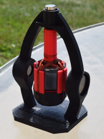
Revisiting Mendocino Motors
Some time ago, we had a great time making a two-part series describing a Mendocino motor. It's a simple demonstration motor that spins, powered by sunlight. Made with magnets, insulated wire and a few solar panels, it's a really cool project.
Over the course of explaining and demonstrating how it works, we created a rough prototype to demonstrate the pieces. It wasn't pretty, but worked well enough to show the concepts. Since then, we've been asked about how to build a better one, and what magnets should be used.
Here's our second try!
What did we learn last time?
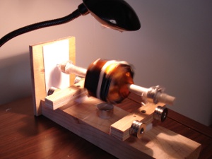
The demo we built last time was okay, but there are things we could have done better. We used a lot of wire, which resulted in a really heavy rotor. Copper is heavy - who knew? It was hard for this heavy rotor to get started. Less wire would have been better.
The other problem we found was that the levitating rotor wasn't very stable. When spinning at slow speeds, the rotor tended to wobble quite a bit. If the wobble motion got too large, it could throw itself off. Unless you build something to constrain the rotor from flying off, this isn't something that you can build and expect to just leave on your windowsill.
A Magnet House Divided
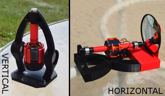
In proposing a better design, we found ourselves divided into two camps. One side wanted to make a vertical motor configuration, where the spinning rotor hangs down. The other side wanted to stick to the horizontal configuration with its pseudo-levitation, arguing that the cool-factor of this was an essential part of the demonstration.
In the end, we built examples of both. We found pros and cons for both.
Show me the Videos!
Here's the new, vertical-axis Mendocino Motor in action:
Here's the more common Mendocino motor, with the rotor axis in a levitating, horizontal position.
Why Does it Spin?
There's a great technical explanation about how and why these things spin in our original Mendocino Motor article. Here's the short explanation:
- Sunlight hits the solar panel, which generates a voltage.
- The solar panel is hooked up to a coil of wire, which now has a current running through it.
- With a strong magnet or magnets nearby, the coil is sitting in a strong magnetic field.
- When a current is run through the coil of wire that's sitting in a magnetic field, a force acts on it. In these setups, it's a brief burst of torque turning the rotor in the moment that sunlight is shining on the panel.
This explanation is true for both the vertical and horizontal motors we made.
Which orientation is better, horizontal or vertical?
Even after building these two working motors, opinions here are still mixed. The vertical setup is easier to recreate, more forgiving, and works quite well. For something that's going to sit on a windowsill and just run, however, it's often not facing in the right direction. The horizontal motor is more apt to just spin as long as sunlight is shining in the window.
If you've built one of these motors, please let us know. Share your pictures, and maybe we'll add some of the best here!
More Detailed Build Instructions/Details
Vertical Mendocino Motor
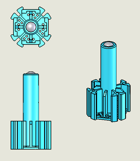
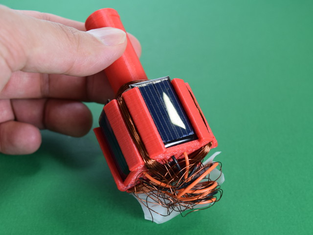
In the picture, the plastic rotor is shown in blue. A 1/2" diameter steel ball, NSB8, is shown inserted up inside the hollow cylinder. This will stick to another steel ball above it in the final assembly, making a low friction support.
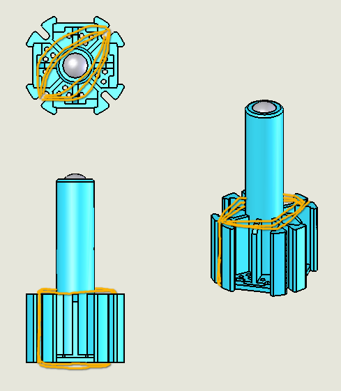
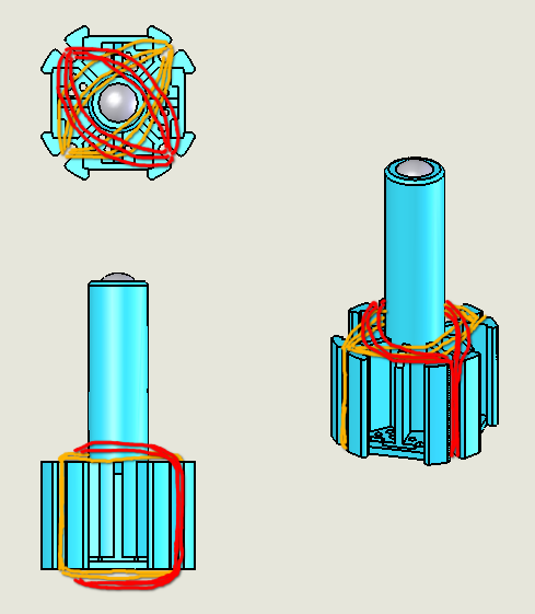
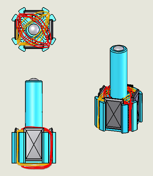
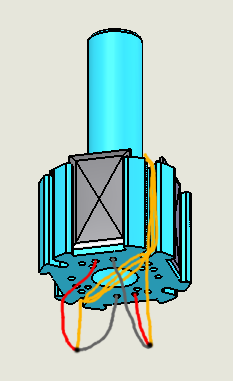
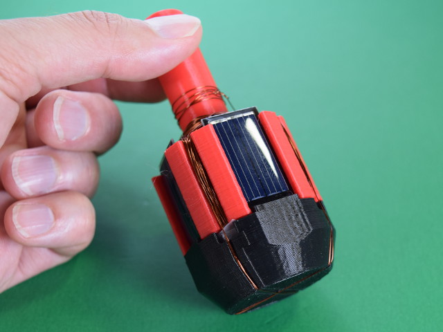
One loop of wire is connected to two of the solar panels that are opposite one another as shown. One end of the loop connects to the positive wire from one solar panel and the negative wire from the other. Likewise, the opposite end of the loop connects to the remaining wires from the solar panels.
More explanation can be found in our earlier article.
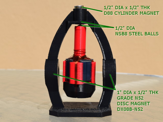
In the top of the frame, a 1/2" diameter steel ball is dropped into the top (not visible). A strong, 1/2" diameter x 1/2" thick D88 magnet is set on top of the ball, sticking together. This makes enough magnetic attraction to the steel ball in the rotor, so that the steel balls stick together. We like this solution since it minimizes the contact area. It doesn't have spinning parts rubbing against a magnet. Steel balls are a lot tougher than neodymium magnets!
Two powerful 1" diameter x 1/2" thick DX08B-N52 magnets are set on either side of the rotor, attracting towards one another. This provides a strong magnetic field where the rotor is, in a fairly uniform direction.
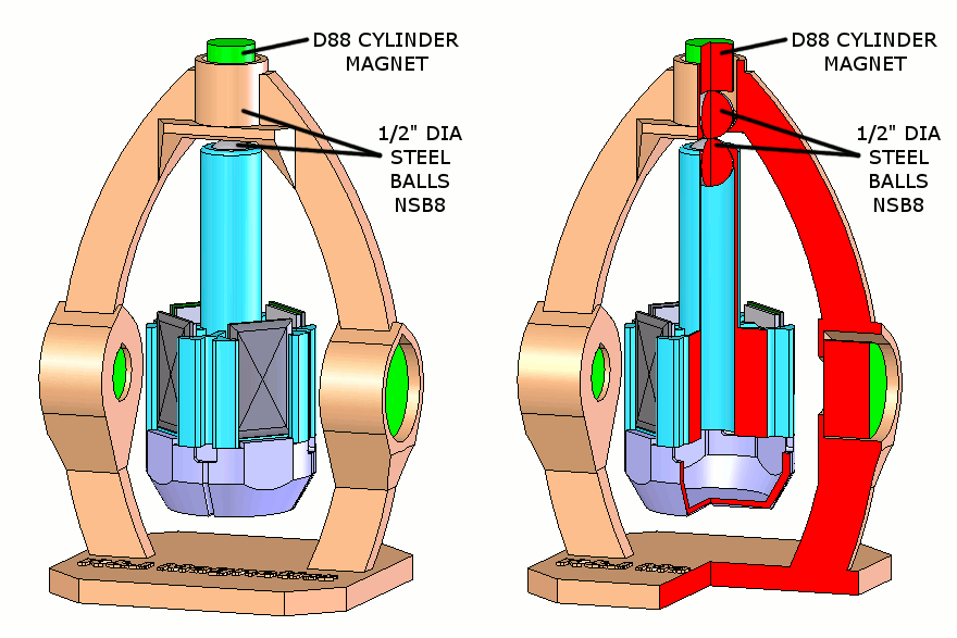
A 1/2" diameter NSB8 steel ball is dropped into the top. A strong, 1/2" diameter x 1/2" thick D88 magnet is set on top of the ball, sticking to it. This makes enough magnetic attraction to the steel ball in the rotor, so that the steel balls stick together. We like this solution since it minimizes the contact area. It doesn't have spinning parts rubbing against a magnet. Steel balls are a lot tougher than neodymium magnets!
In this configuration, the spinning rotor hangs down, making it quite stable. Even if uneven forces push it to the side, gravity tends to keep it hanging down.
Cycle through the pictures to check out our design. We used 30 gauge magnet wire and some inexpensive solar panels from Jameco, which had dangling wires included. They aren't the biggest, but they're affordable. Plus, they come with two wires dangling off, so that no soldering was required!
The structure was printed on a 3D printer. It's a great way to create parts that are accurate and balanced well, though not strictly necessary. You could build a similar device with other materials for your own project. If you'd like to use our 3D model shapes, you can download them here:
- Rotor, Vertical Mendocino Motor
- Wire Cover, Vertical Mendocino Motor
- Support, Vertical Mendocino Motor
You'll also need:
- 30 gauge magnet wire
- 2x NSB8 steel balls
- 1x D88 cylinder magnet
- 2x DX08B-N52 disc magnets, to provide the strong field.
Vertical Results
In bright light or strong sunlight, this motor works quite well. To get it to spin in moderate sunlight, we used some very powerful magnets on the sides. The 1" diameter x 1/2" thick DX08B-N52 discs provided a strong field in the gap between them. Be careful handling powerful magnets this large!
This thing spins great. It's a wonderful demonstration that gets a lot of oohs and aahhhs. That said, there are still some drawbacks that we'd love to improve:
- Those are big, powerful magnets on the sides. They shouldn't be loose anywhere kids might get their hands on them. Something should be done to contain and lock them in place, to avoid worries about getting hurt if someone slams the two powerful magnets together.
- It only works at some angles. The magnets have to be at about a 45° angle to the direction of the sunlight. If not, it won't spin.
- Because the rotor only has two windings, sometimes it won't start spinning on its own. Depending on the start position, it might need a little spin by hand to get it started. While more complex, a larger assembly with 6 solar panels and 3 windings might address this. A hexagon shaped motor would be neat!
Horizontal Mendocino Motor
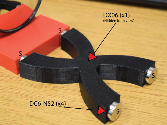
A mirror provides a vertical, low friction surface as a wall for the spinning rotor to lean against.
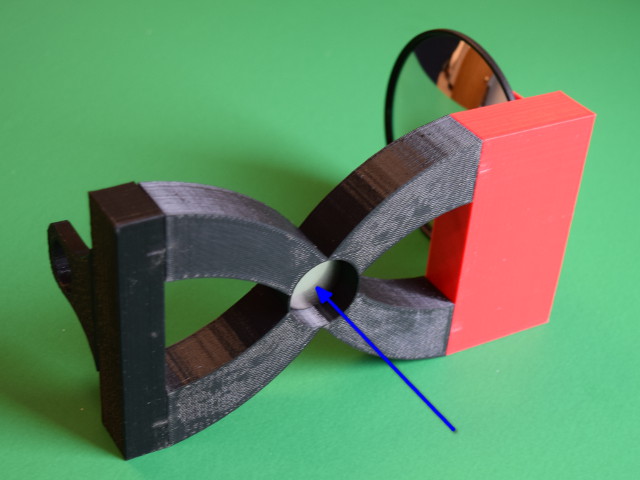
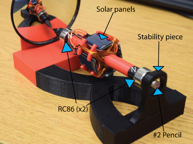
The center shaft of the spinning rotor is made with a common pencil. It's a nice, straight axle to work with, and comes with a low friction graphite tip!
At either end of the shaft are RC86 ring magnets, pressed in place over the shaft's 3D-printed body. When set with their poles pointing in the same direction as the two magnets in the base below them, a repelling force is felt between them. This is what holds up the rotor.
In the middle of the rotor is an assembly of four solar panels and two windings of copper wire. This construction follows the same idea as described earlier for the vertical motor.
Our earlier horizontal Mendocino motor was constructed out of magnets screwed to scrap wood. It was far from perfect or stable. We assumed that much of the stability issue could be solved by holding the magnets in a more square, stable, tighter-toleranced and repeatable way. Armed with a 3D printer, we figured we could print a base to hold the magnets exactly where we wanted them.
Back when we first described these motors, we dedicated the whole first article to describe how the floating rotor is held, balanced and supported. It's a touchy thing, requiring the right magnets and distances to be stable.
In this round, we found that even with a higher precision setup, getting it to balance was still challenging. Don't expect to construct one of these things and have it just work right away. It takes a lot of fiddling with the positions of the magnets to get things just right.
Here are the 3D model files you see in these photos:
- Mirror Holder, Base
- X-Shape, Base
- End Cap, Base
- Stabilizer, Base
- Rotor Spindle, 2x
- Spacer, Rotor
- Spacer, for revision to RC86 magnets
You'll also need the mirror, the pencil, the 30 gauge magnet wire and the magnets:
- 4x DC6-N52 disc magnets for the base
- 1x DX06 disc magnet under the base, to provide the strong field
- 2x RC86 ring magnets on the rotor
Horizontal Results
After getting the balance right, we ended up with a really nice result. It looks great and performs well.
Ultimately, we still aren't 100% happy with the stability. Like many magnetic levitation ideas, this stuff is harder than it looks.
Left alone, the rotor can wobble enough during startup to break free and slam to attract to the base magnets. To address the problem, we added a feature that constrains the end of the rotor. It's a small detail, but an important one for safe operation. It prevents the floating part from flying loose and damaging anything.


